1 Foreword
The cable industry is currently experiencing a development of higher technology, including production automation and mechanical equipment simplification. In the cable industry, Auto pay-off track is the most widely used and is a kind of mechanical equipment that has high requirements on the control of the inverter. In the Auto pay-off track, the PID two-way adjustment function is generally used, requiring the built-in PID function of the inverter and can realize two-way control.
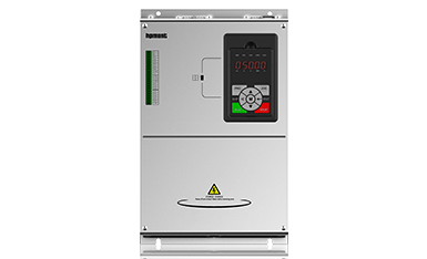
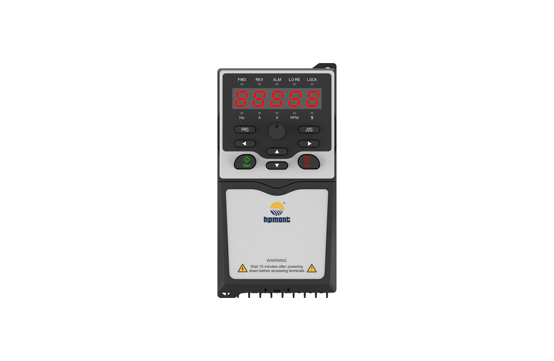
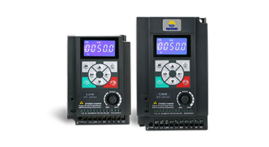
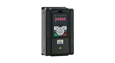
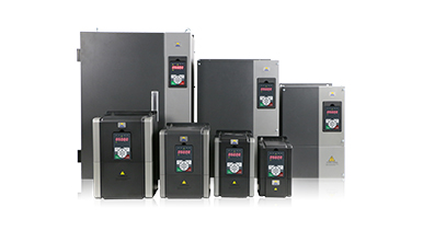
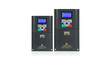
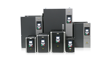
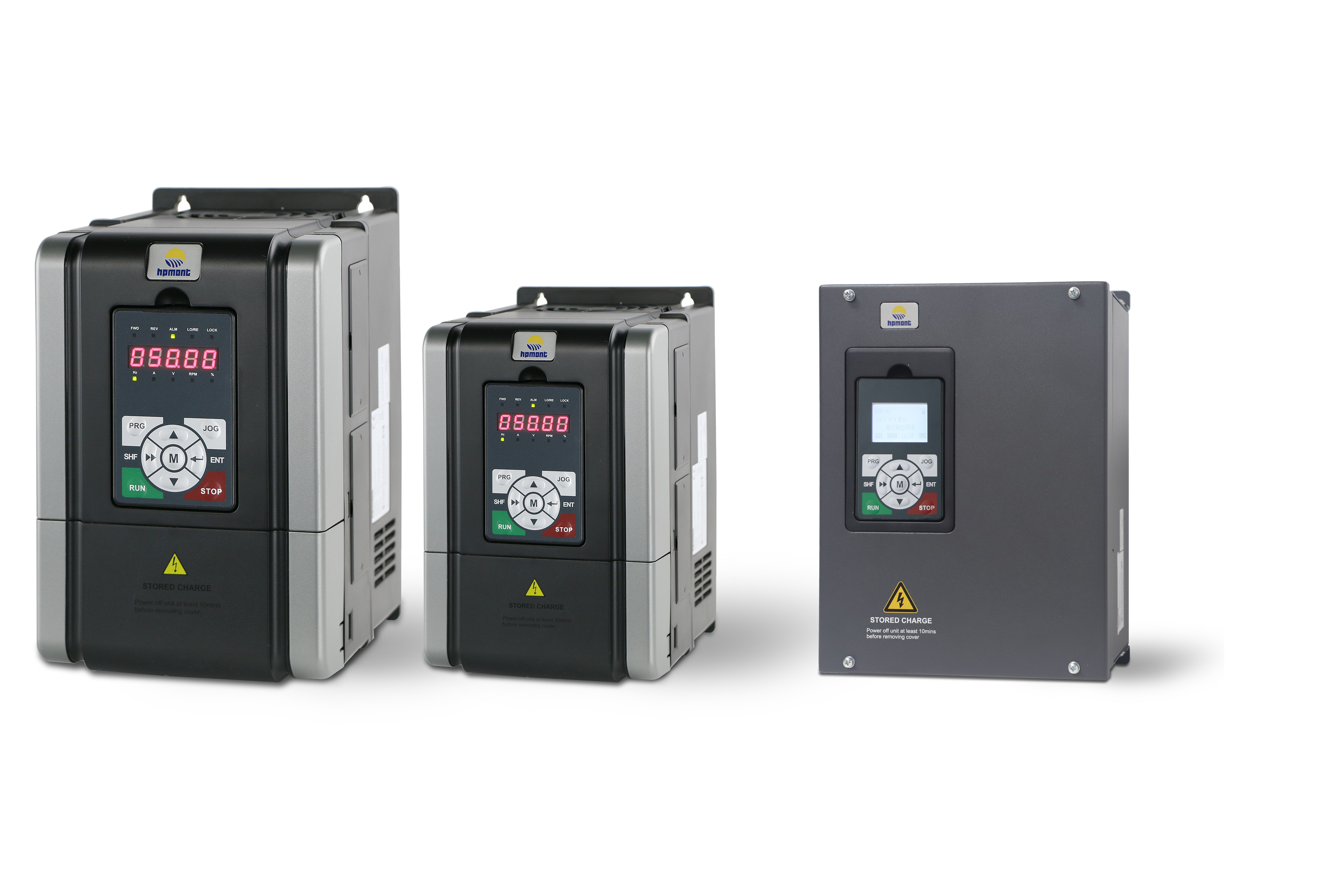
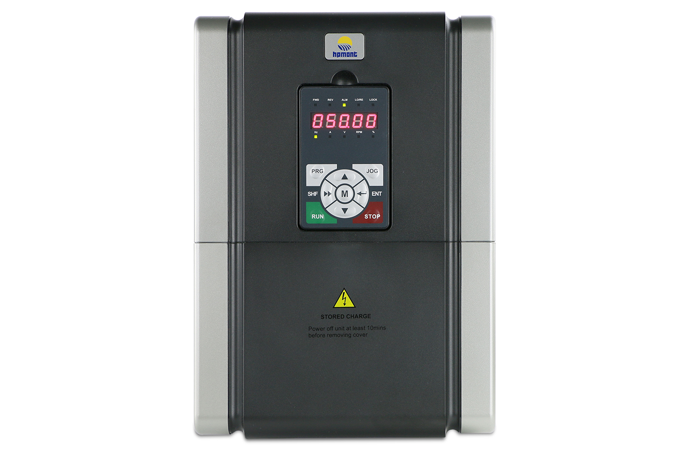
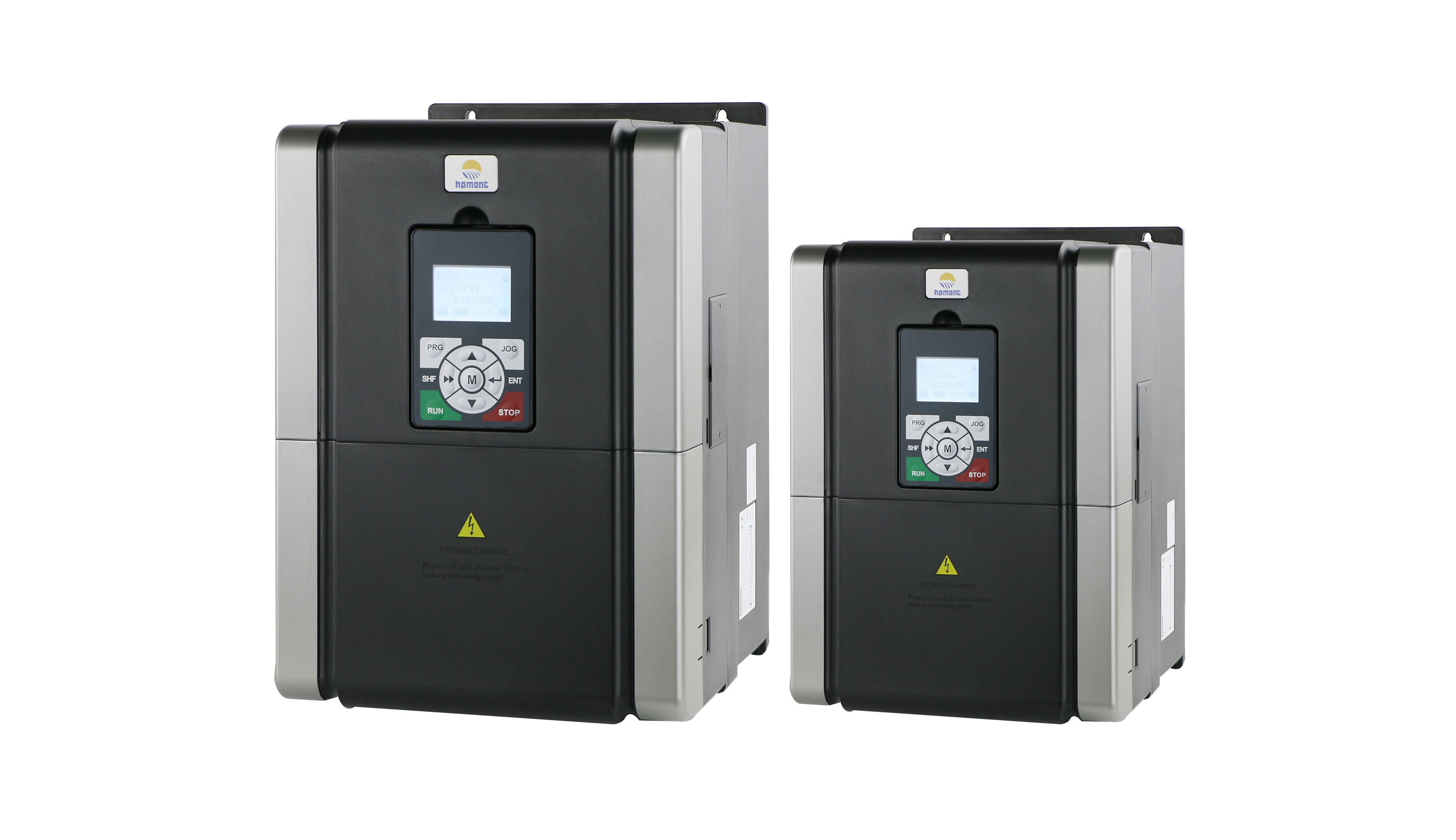
The built-in PID function of the Hpmont HD20 meet these requirements well. It is prominent among the whole industry for its excellent vector control performance and high stability and reliability.
2 Technical requirements for Auto pay-off track
As an essential in the cable industry, the Auto pay-off track should meets the following requirements:
a.High simulation accuracy ,making the feedback signal of the pendulum position sensor can be accurately detected;
b.Fast PID adjustment speed, responding quickly to changes in the speed of the line releasing to ensure it normal;
c. High stability, keeping the speed of the releasing line stable and reduce the cable tension fluctuation;
d. Two-way control,adjusting the lines according to the actual situation.
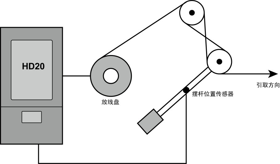
3 Application case in Auto pay-off track
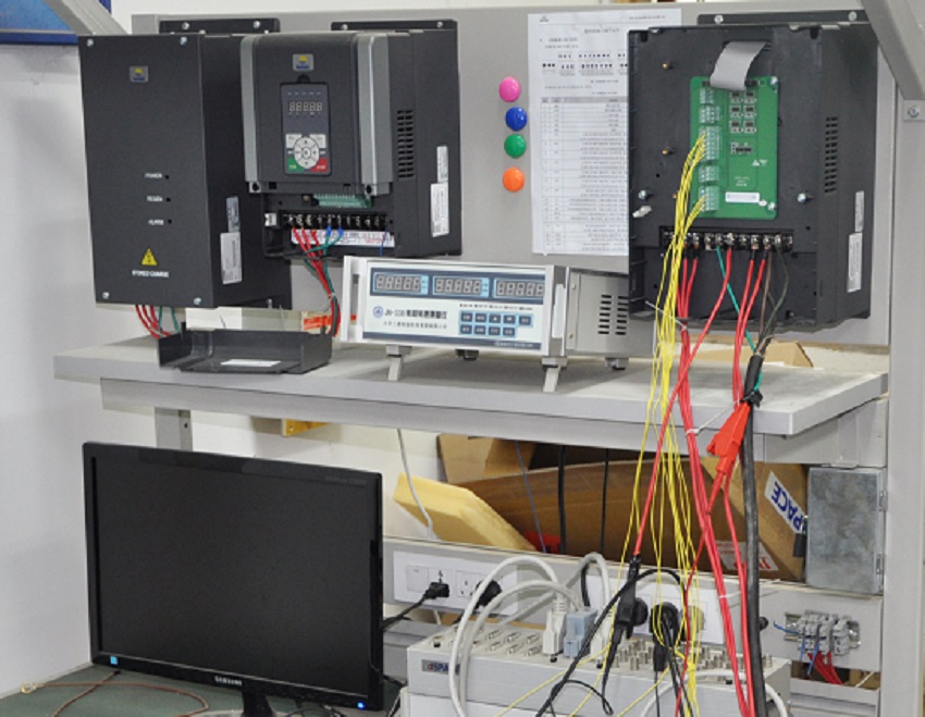
The equipment used in this application is a chemical foaming extruder, along with the diameter of 3 mm copper wire . Since the diameter of the copper wire is thin and fragile, it is very difficult to control the discharge line. The debugging process and effects are as below:
3.1 Field wiring
The command channel of the inverter is given by the terminal; the output of the pendulum position sensor is 0-10v signal, which is used as the PID feedback signal; the PID setting is set by the number. The specific wiring is as shown below:
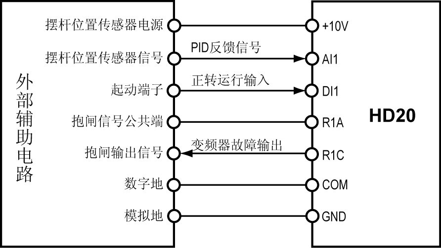
3.2 Debugging announcements
(1) Since the vector control of the low frequency torque and the steady speed accuracy are better than the V/f control, it is preferable to use vector control on the power take-up frame.
(2) Since the vector control process needs to accurately obtain the motor parameters, it is necessary to input the motor nameplate value accurately and perform motor parameter manually.
(3) Since the position of the pendulum is in equilibrium, it is determined that the corresponding feedback signal is also determined, and all the given channels of the PID are set to digital.
3.3 field debugging
(1) wiring according to Picture 2;
(2) In order to obtain better motor drive performance, it is necessary to set the motor parameters according to the motor nameplate, and then set F00.01 to 2, that is, the speed control mode is selected as PG-free vector control, and finally the parameter self-tuning is performed;
(3) Set the maximum frequency and the upper limit frequency according to the actual transmission relationship in the field;
(4) Set the command given channel and frequency given channel;
(5) Set the acceleration and deceleration time;
(6) set the analog function;
(7) Setting the terminal function;
(8) Enable the PID function and adjust the PID parameters according to the field performance;
(9) The final parameter settings are as follows.
3.4 debugging effect
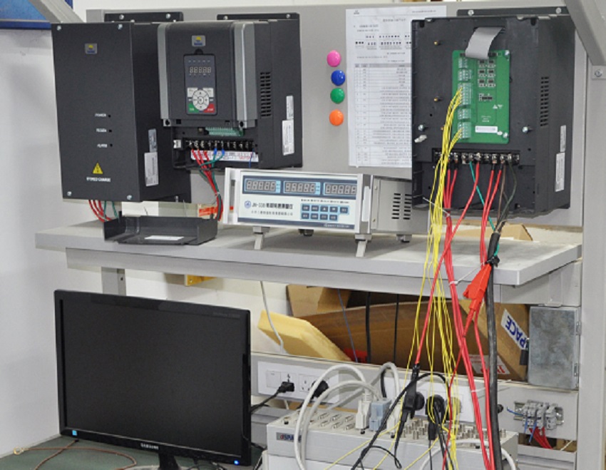
Testing of low-speed pay-off, accelerated pay-off, high-speed pay-off and decelerated pay-off are proceeded, and we find that during the acceleration and deceleration process, the pendulum have slight fluctuations, and in the constant speed process (including high speed, low speed), the pendulum position remains a good balance. All the wire-drawing process, the cable tension is constant and uniform, and it is well received by customers.
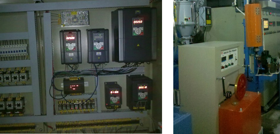
Picture 3:performance scene
4 Summary
The HD20 vector control inverter has been successfully applied in the field of Auto pay-off track. Its superior performance (fast response PID function, wide speed range, high steady-state accuracy, fast acceleration and deceleration, flexible and convenient operation, multi-functional protection) and high reliability have been fully verified to meet the needs of the Auto pay-off track.

