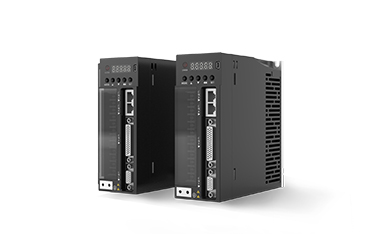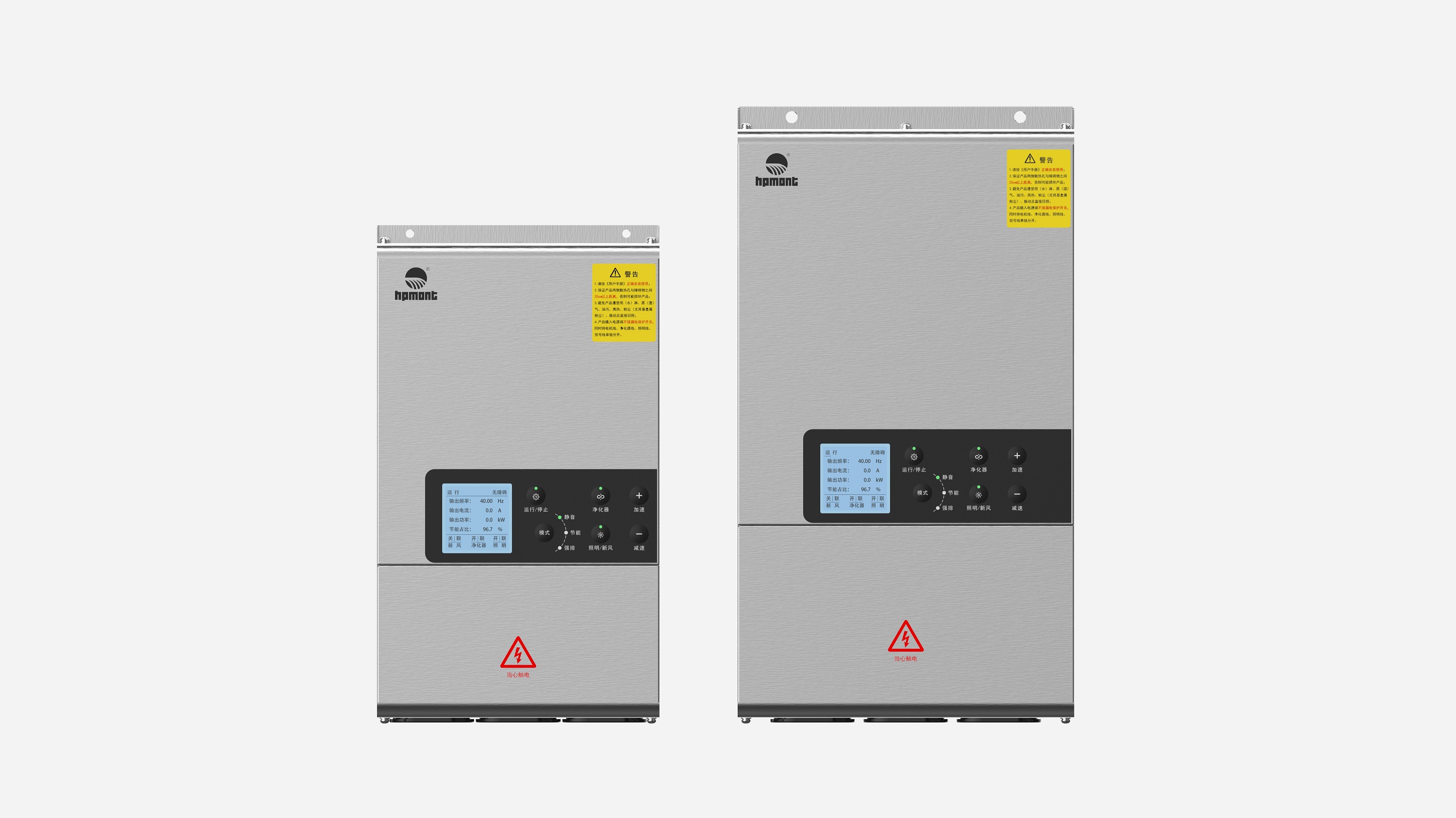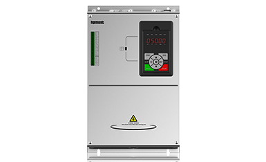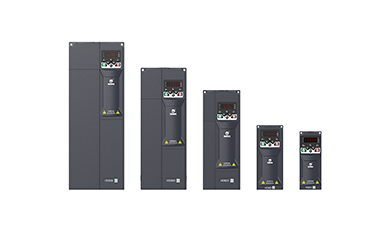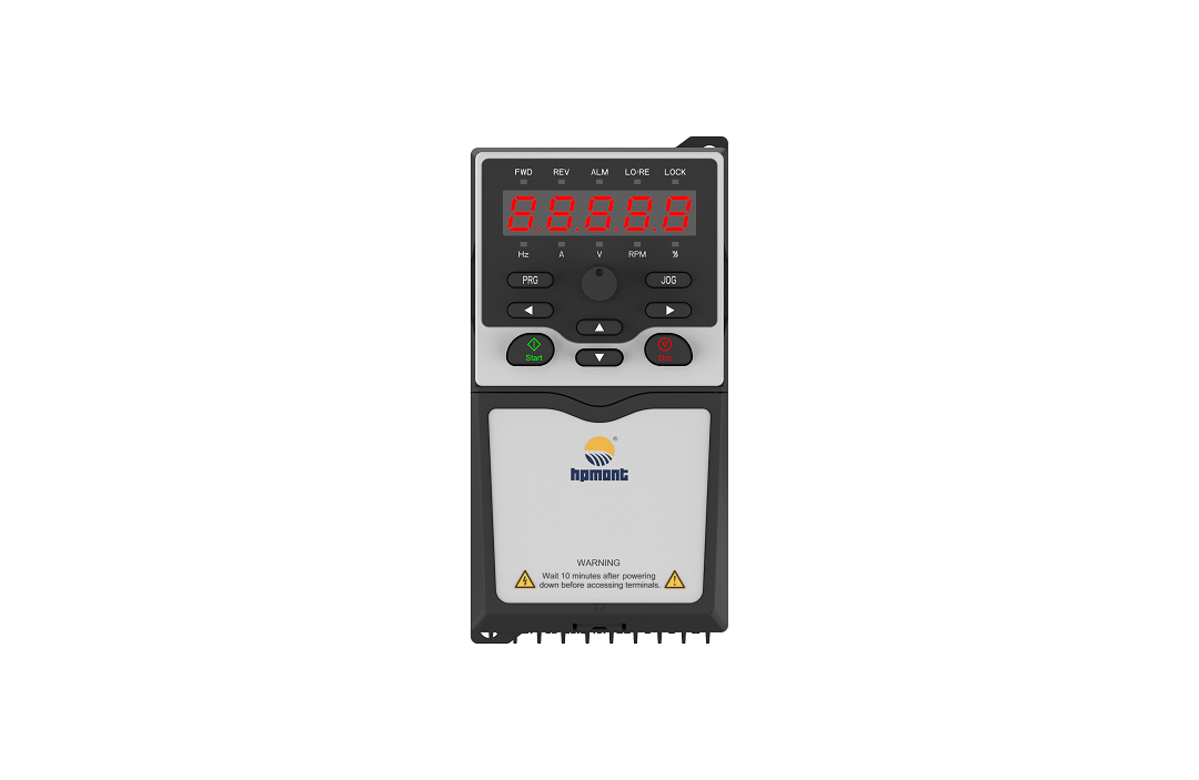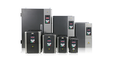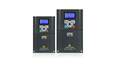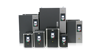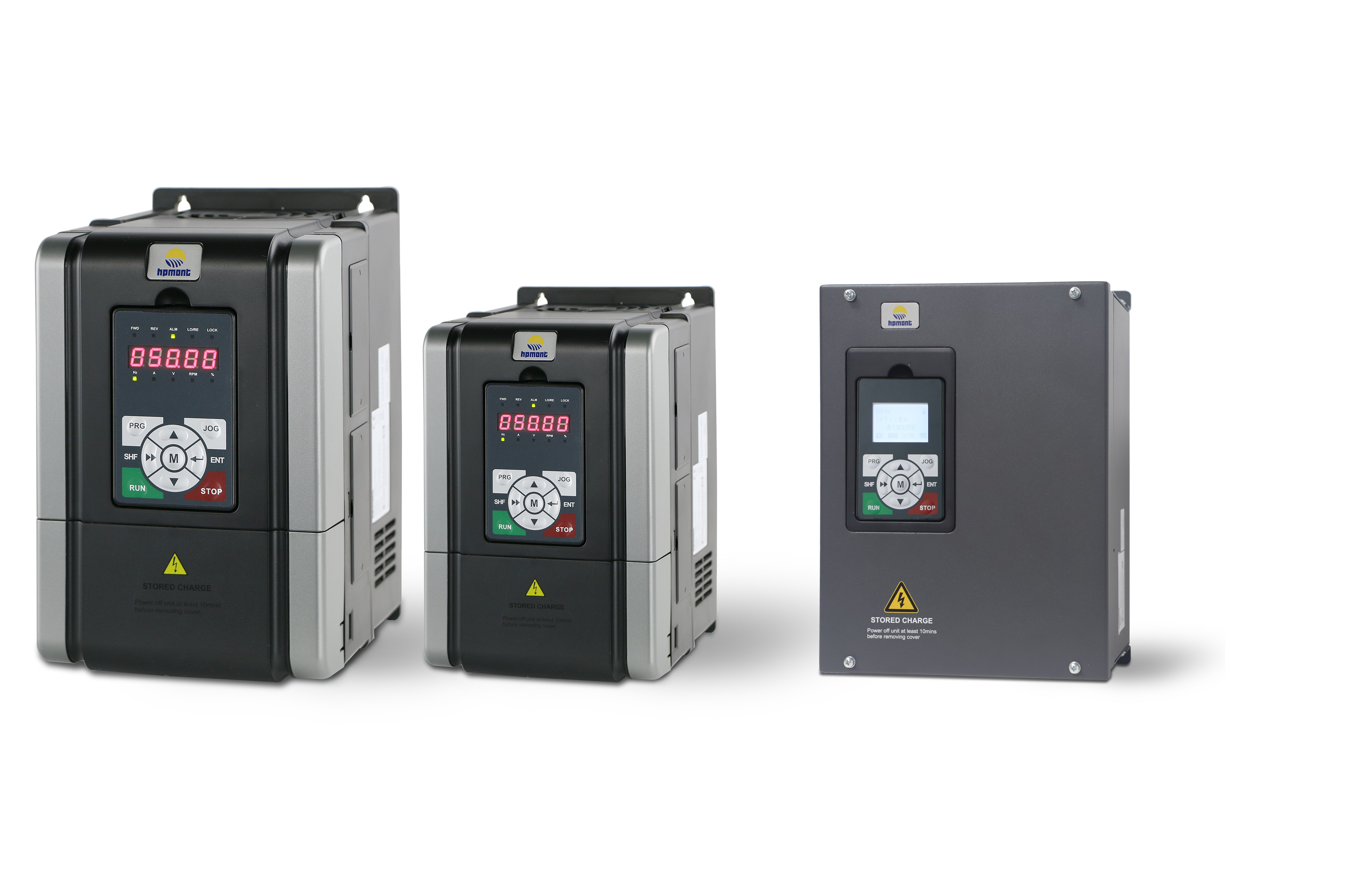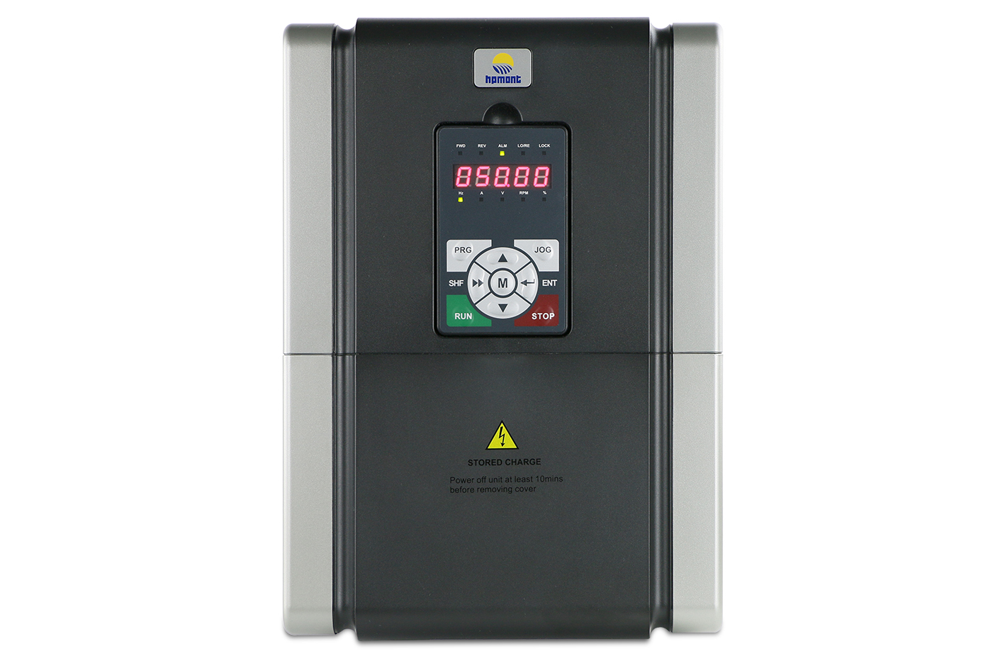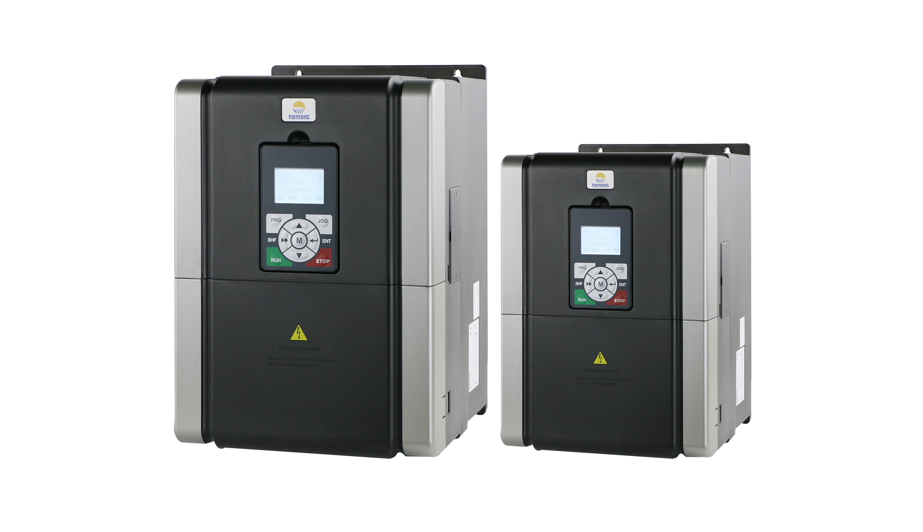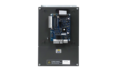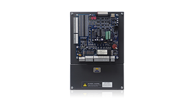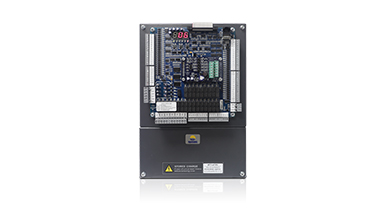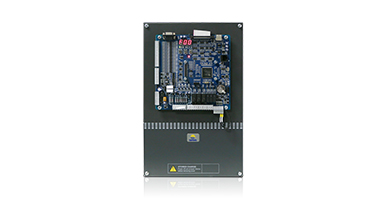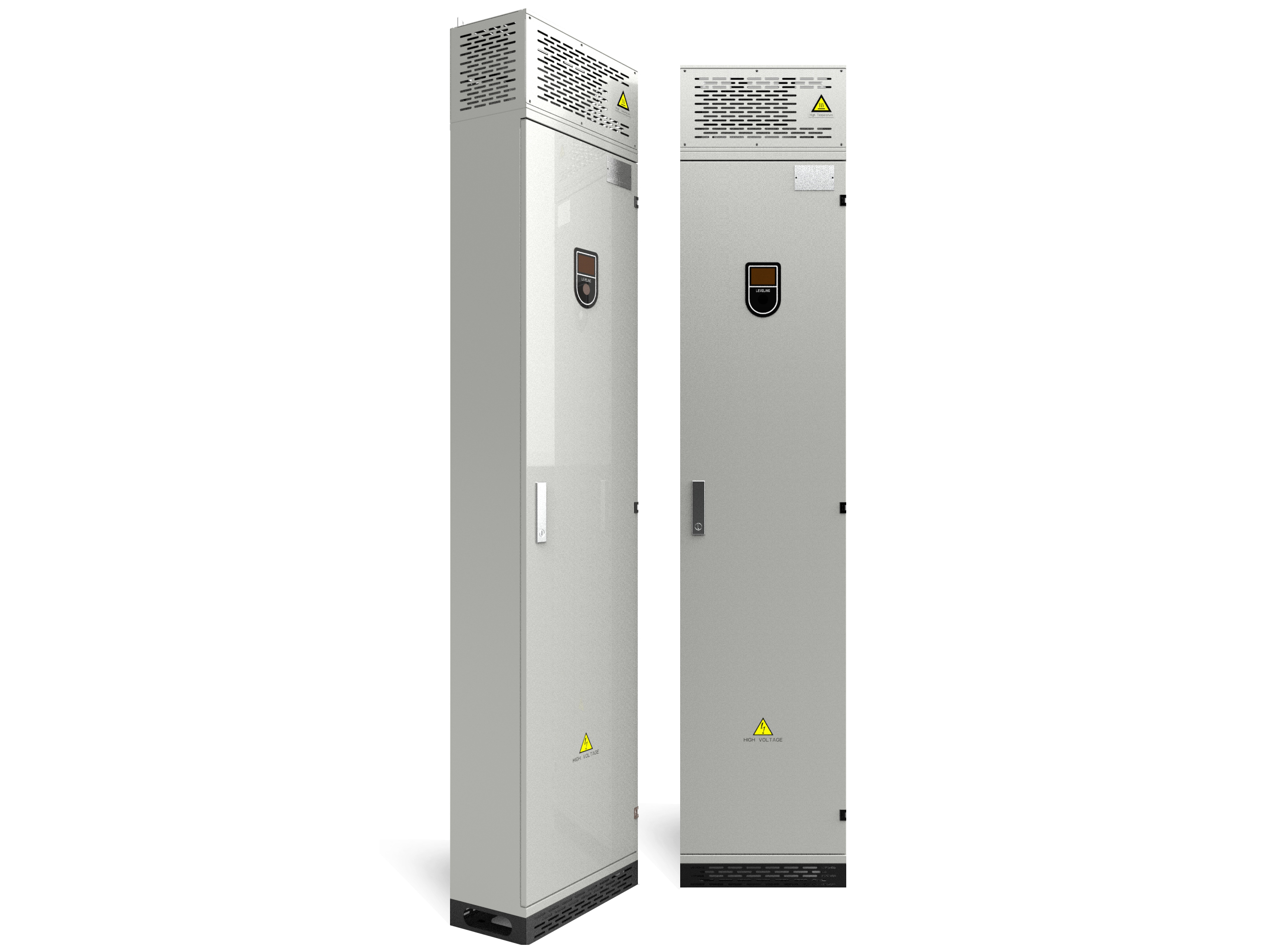
Abstract: This paper briefly introduces the application of Hpmont HD50 inverter in straight-through wire drawing machine. The working principle and working process of the straight-through wire drawing machine are expounded. The configuration, simple debugging process and advantages of the direct-feed wire drawing machine frequency conversion control system are introduced from practical application.
1 Foreword
The straight-through wire drawing machine is a kind of non-sliding continuous wire drawing machine with high speed, high efficiency, no bending, no twisting, strong cooling and excellent cost performance. It has been widely used in developed countries and regions such as Europe and America. However, it is a weak link in China, and the mechanical and electrical equipment is obsolete, which hinders the development of the industry. Although the straight-through wire drawing machine has absolute superiority in terms of production efficiency, production cost and product quality compared with the pulley wire drawing machine, its expensive one-time investment has made many domestic metal products companies discouraged.
Now with the advancement of process technology and the popularization of frequency converters, frequency conversion control has begun to be widely used in straight-through wire drawing machines, and PLC can be used to realize drawing type setting, operation automation, production process control, real-time closed-loop control,automatic metering and other functions.
2 Features of HD50
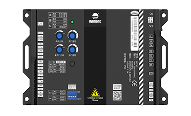
Hpmont frequency inverter adopts magnetic field directional current closed-loop vector control mode, adopts TI's advanced 32-bit motor control dedicated DSP, and the main frequency reaches 150M, which can complete complex vector control algorithms at higher speed and more precision
Overload capability: 150% rated output current for 2 minutes; 180% rated output current for 10 seconds
Drive motor type: AC asynchronous motor, synchronous motor
Control mode: V/f control; open loop vector control (SVC); closed loop vector control (VC)
Operation command setting mode: operation panel setting; external terminal setting; set by the upper computer through the SCI communication port
Speed setting mode: digital setting, analog setting, SCI communication setting
Speed setting resolution: Digital setting: 0.01Hz
Analog setting: 0.1% × maximum frequency
Speed control accuracy: ±0.5% (SVC); ±0.05% (VC)
Speed control range: 1:100 (SVC); 1:1000 (VC)
Torque control response: <200ms(svc);<50ms(vc)< span="">
Starting torque: 180% rated torque / 0.5Hz (SVC); 180% rated torque / 0Hz (VC)
Torque control accuracy: ± 5%
3 Working principle
The straight-through wire drawing machine is a small continuous production equipment consisting of a plurality of drawing heads. By drawing it step by step, the wire can be cold-drawn to the required specifications at a time, so the working efficiency is relatively high. However, since the wire diameter of the wire changes after each stage of drawing, the working line speed of each drawing head should also vary.
The drawing speed of each drawing head also changes depending on the configuration of the die. The drawing speed is based on the second flow volume of the wire passing through the die at each moment, even if the formula holds: πR2 × V1 = πr2 × V2, where:
R: diameter of the incoming wire; R: diameter of the outgoing wire; V1: linear velocity of the incoming wire; V2: linear velocity of the outgoing wire
The working speed of each drawing head of the straight-through wire drawing machine is based on the above formula, ensuring that each drawing head operates synchronously. However, the above description is only based on the steady state working process of the ideal state. Due to the error of the mechanical transmission and the gap of the mechanical transmission, in the dynamic work of starting, accelerating, decelerating, stopping, etc., the respective drawing heads cannot be synchronized. Therefore, we use a displacement sensor on the straight-through wire drawing machine to dynamically measure the tension of the wire between the various drawing heads, and then convert the tension into a standard signal (0/4-20mA or 0-10V), and feed back to the speed-regulating frequency conversion. After receiving the signal, the inverter is used as a closed-loop PID process control, superimposing the adjustment amount of the PID calculation on the main speed, keeping the tension of each tension detection point constant, and ensuring that the straight-through wire drawing machine in the synchronous constant tension status.
4 Frequency conversion control system configurations of straight wire drawing machine
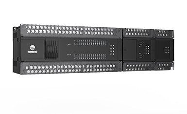
The system logic control of the straight-through wire drawing machine is more complicated. There are various linkage relations realized by PLC, and the synchronization control is all realized inside the Hpmont HD50 inverter. The system configuration is shown in Figure 1:
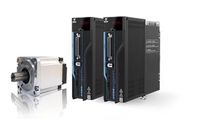
There are 11 tower wheels on the machine platform, among which 1#--10# adopts the special inverter of Hpmont HD50 wire drawing machine, corresponding to the displacement sensor. The displacement sensor feeds back the current signal of the inverter 4-20mA, and the inverter ensures the constant tension of the wire.
11# adopts the Hpmont HD50 special inverter for wire drawing machine, without tension mechanism.
12# is also controlled by the Hpmont HD50 special inverter for wire drawing machine. Unlike the 1#-10#, the winding diameter of the wire spool is constantly changing, and at the same time the tension of the wire should be constant to avoid line broken .
Working process: According to the working speed set on the touch screen, the speed signal enters the PLC, and the PLC outputs the analog signal according to a certain slope after considering the time of acceleration and deceleration. This is mainly to meet the needs of some operations such as jogging and threading. The analog voltage signal output by the PLC is simultaneously connected to the AI1 input of all the inverters as the main reference signal of the speed. The signal of each swing arm displacement sensor is connected to the AI2 of the corresponding drum drive inverter as a feedback signal of the PID control. And then setting a given value of PID according to the position of the swing arm. The system is a very typical PID control system with feed forward and the PID is used as a fine adjustment amount.
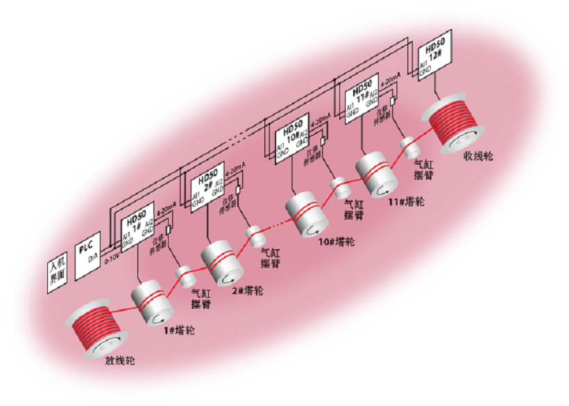
Figure 1 Schematic diagram of the straight-through wire drawing machine system
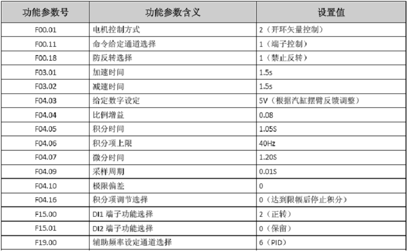
Perameter settings:
5 Summary
After optimizing the parameter values, the speed of the equipment test machine is 650 m / min, and that completely solves the problem that the original plate is unstable under the high speed. Through the comparison test under various working conditions, the performance of the wire drawing machine with imported DC drive is the same, and the equipment efficiency and power saving rate are obviously improved. Moreover, the electrical device configuration of the system is concise and logically clear, and the cost is still greatly reduced compared with the original, which is a very cost-effective solution.

